|
The
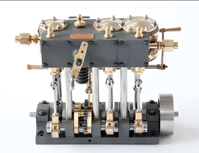
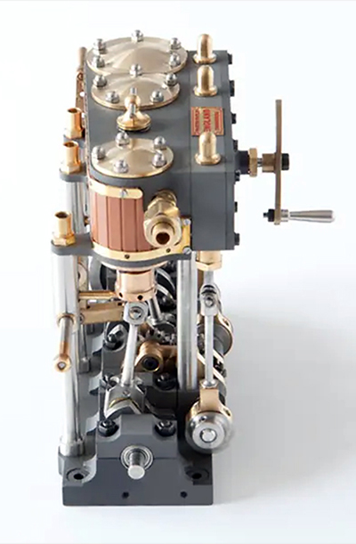
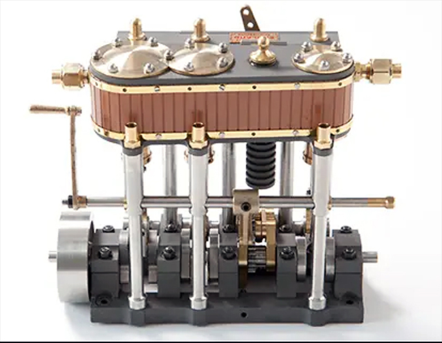
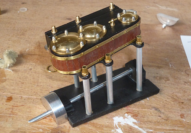
engine isn't included in the plans, so before starting work you'll need to draw an accurate
scale plan and elevation of the engine from these photos >>> The size of the original engine is as follows:
Draw your plans to the scale you require. (Photos courtesy of Martin Bayliss)
|
|
||||||
|
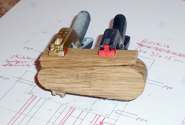
The engine block is made from two small blocks of hardwood, finished on a disk sander to the exact size and shape required. |
 |
||||||
|
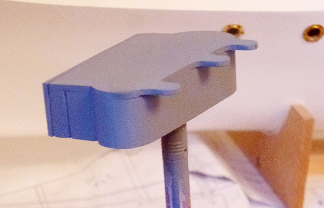
2mm plastic sheet is used to make the base of the block. This extends outwards in three places to provide the 'tab' mounts for three of the supporting rods later. Another piece of 2mm plastic sheet fits on the side of the block (on the left in the photo). Detail is important so file in grooves as required. The photo shows the engine block upside-down after being sprayed with grey primer. Sand and add further coats of primer until a smooth finish is obtained. With reference to your plans:
a) Drill three holes in the top to locate the three cylinder heads, three holes to locate the little brass widgets that go alongside them, and one for the 'tap' between cylinder heads 2 and 3.
b) Drill a small hole in each end of the block to accommodate the 'steam pipes' that will be fitted later.
c) Calculate the positions of the six aluminium supporting rods and drill 4mm diameter holes for each of them in the underside of the block. There will be one in each plastic tab projecting from the block's base, and three in the block itself. d) Drill 12 tiny holes in the flat side for the steel bolts that will be fitted later. Spray the assembly satin black to finish. |
 |
||||||
|
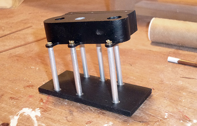
The
engine base is a simple rectangle of 4mm ply, just wide enough to fit through
the gap in the forward well deck. Mark and drill six 4mm holes to match those in
the underside of the block, noting how the angle affects the spacing. The base and block are joined by six 4mm diameter aluminium tubes. These fit between the holes drilled in the base and the underside of the block. Take time to get them all parallel and in the correct positions. Where the tubes go through the three tabs, cut them flush with the top. These are completed with small pieces of brass tube that fit into the aluminium tube, finished with brass nuts that have been drilled out to fit. In this photo the block and base are having a trial alignment. |
 |
||||||
|
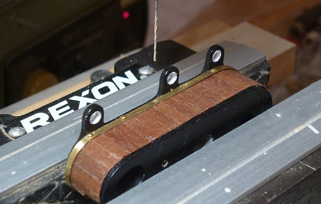
When
you're satisfied that the engine block and its base fit together correctly, take
them apart so you can make and fit the wood cladding. This is made from strips
of 3x0.6mm mahogany cut to the exact length required. I found it easier to
assemble by gluing them onto thin paper first, sanding and spray varnishing,
then gluing the competed assembly to the block. Shape two thin 3mm brass strips to fit around the top and bottom of the block and drill holes for the brass pins which will hold the strip in place (you may find it easier to drill the strips first). Cut the pins about 5mm below the head and superglue them in place.
|
 |
||||||
|
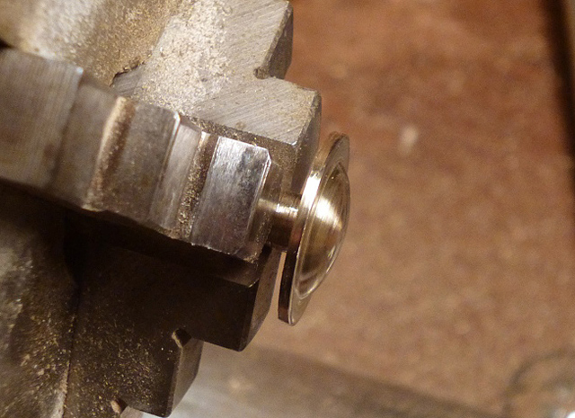
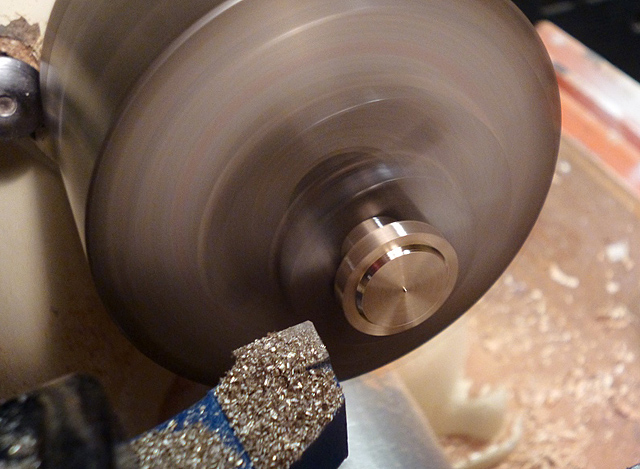
The
three cylinder heads are turned from brass rod, leaving a short peg underneath
so they locate in the holes you drilled earlier.
The two largest ones need to be flatted on one side; I used a disk sander for this. |
|
||||||
|
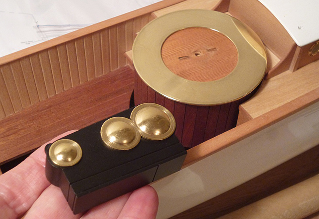
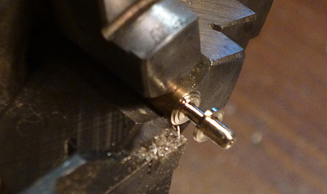
Turn
the three little brass widgets that go alongside each cylinder head and glue all
the heads and widgets in position. Make the 'tap' from a handrail stanchion and short length of thin brass rod and glue it in place. |
 |
||||||
|
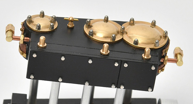
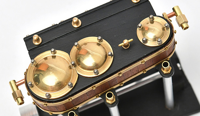
Using
tweezers, carefully superglue the miniature acorn nuts around the edges of each
cylinder head, and the 12 miniature nickel bolts into the flat side. This photo of the finished engine shows all the minor details. |
 |
||||||
|
I
decided not to replicate the con-rods and crankshaft, choosing a simple but
visually effective alternative using 3mm aluminium rod and a mock flywheel. First, make and fit wooden bearings for each end of the crankshaft, making sure they hold the rod at the correct angle to line up with the propeller. Cut the aluminium rod to length and put an acute angle on the rear end so it sits flat on the keelson. The flywheel is turned from a 25mm diameter piece of aluminium rod, then cut approximately in half so it sits neatly on the sub-floor below the forward well deck. |
 |
||||||
| You can now assemble the block and base for the final time. To complete, make and fit the steam pipe fittings at each end of the block. These are made from 2mm copper rod, 3mm brass rod and 4mm hex bar, cut and drilled to resemble couplings. |
 |
||||||
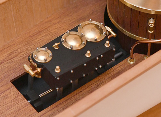
| When you're satisfied that all parts of the engine assembly have been made as well as you can make them, glue it in place on the sub-floor below the forward well deck making sure the crankshaft is on the centre line. |
 |
||||||
|
|